Design & Engineering Lead
1 Week September 1-7 2026
Overview & Problem Statement
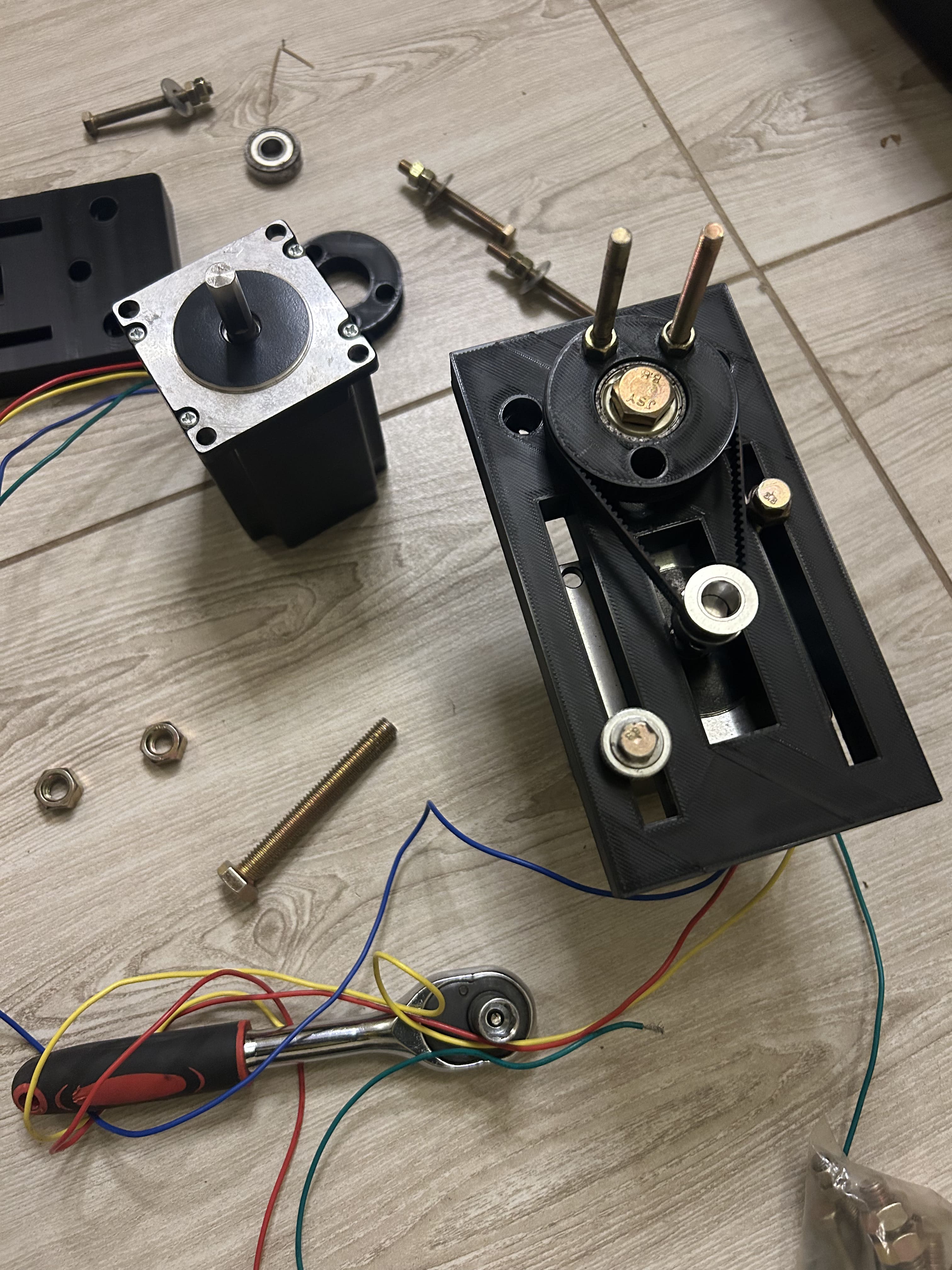
Joint 1 is the base rotation stage of the 6-axis robot arm, built as a belt-reduction gearbox. A NEMA 23 stepper drives a small pulley which turns a 70-tooth GT2 on the output shaft, trading speed for torque, exactly what the base joint needs to hold the position under load.
System Architecture & Technical Approach
Everything mechanical is 3D-printed except fasteners and the bearing. The motor bolts into a 3D-printed mount with screws; the output rides on a 608z bearing, clamped by a single screw that also secures the pulley.
Full BOM and print files are attached below
Hardware & Software Implementation
#include <Arduino.h>

// ---- Pin mapping (matches the wiring we set up earlier) ----
const int PUL_PIN = 4;   // -> DM556 PUL+   (PUL-/DIR-/ENA- tied to GND)
const int DIR_PIN = 5;   // -> DM556 DIR+
const int ENA_PIN = 6;   // -> DM556 ENA+   (optional)

// ---- Motion settings ----
// Full steps per motor revolution (1.8 deg motor = 200). If you set
// microstepping on the DM556 DIP switches, multiply accordingly
// (e.g. 8x microstepping -> 200 * 8 = 1600 steps per revolution).
const int STEPS_PER_REV = 200;

// Delay between step edges, in microseconds. Smaller = faster,
// but too small can stall or skip steps - raise this if the motor
// buzzes/stalls instead of turning.
const int STEP_DELAY_US = 800;

void doSteps(long steps, bool clockwise) {
  digitalWrite(DIR_PIN, clockwise ? HIGH : LOW);
  delayMicroseconds(5); // DIR must be stable briefly before pulsing

  for (long i = 0; i < steps; i++) {
    digitalWrite(PUL_PIN, HIGH);
    delayMicroseconds(STEP_DELAY_US / 2);
    digitalWrite(PUL_PIN, LOW);
    delayMicroseconds(STEP_DELAY_US / 2);
  }
}

void setup() {
  pinMode(PUL_PIN, OUTPUT);
  pinMode(DIR_PIN, OUTPUT);
  pinMode(ENA_PIN, OUTPUT);

  // Keep the driver enabled. On most DM556 boards, leaving ENA
  // unconnected already enables the motor by default; here we drive
  // it LOW to match that "enabled" state. If your motor won't move,
  // try flipping this to HIGH - enable logic differs slightly by board.
  digitalWrite(ENA_PIN, LOW);

  digitalWrite(PUL_PIN, LOW);
  digitalWrite(DIR_PIN, LOW);

  delay(1000); // give the driver a moment to power up before pulsing
}

void loop() {
  doSteps(STEPS_PER_REV, true);   // one full revolution, one direction
  delay(1000);

  doSteps(STEPS_PER_REV, false);  // one full revolution, other direction
  delay(1000);
}
| Part | Qty | Notes |
|---|---|---|
| 608z Bearing | 1 | |
| GT2 Pulley 20 Teeth | 1 | |
| GT2 belt 6mm 200mm length | 1 | |
| Nema 23 | 1 | |
| Power Supply 48V | 1 | |
| DM 556 Stepper Driver | 1 | |
| Esp32 C3 Supermini | 1 |
Key Challenges & Technical Trade-offs
Printed GT2 pulleys are more sensitive to layer roughness; the belt running on the 3-D printed teeth wears faster than one running on machined teeth
Results, Impact & Performance Metrics
Joint 1 holds position under hand-applied load without stalling and rotates smoothly through its full range with the belt reduction ratio in place. Visually and mechanically, it performs like a commercial belt reduction actuator stage - validating the approach for the remaining 5 joints