Design & Engineering Lead
September 2026
Overview & Problem Statement
Mechanical limit switches are a cheap and reliable way to detect a physical end-of-travel point in an object- a moving carriage, a rotating axis, a door, anything that needs to know when it's hit a hard stop This project covers wiring 2 of them to an ESP32-C3 Supermini and reading the data cleanly in firmware.
System Architecture & Technical Approach
I chose the ESP32-C3 Supermini for its small footprint and low cost; it has more than enough GPIO for 2 switches, with room to spare for future additions.
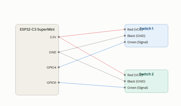
Powering each board from the ESP32-C3's 3.3V RAIL, keeps the signal output within safe GPIO voltage range.
Red => ESP32-C3 3.3V Black => ESP32-C3's GND Green => ESP32-C3 GPIO (Digital Input)
Hardware & Software Implementation
// Limit switch reading with debounce — ESP32-C3 SuperMini
// MakerBot-style powered endstop boards (3-wire: red/black/green)
// No internal pull-up needed — the board outputs its own conditioned signal

const int SWITCH_1_PIN = 4;
const int SWITCH_2_PIN = 5;

const unsigned long DEBOUNCE_DELAY = 30; // ms

bool switch1State = HIGH;
bool switch1LastReading = HIGH;
unsigned long switch1LastDebounceTime = 0;

bool switch2State = HIGH;
bool switch2LastReading = HIGH;
unsigned long switch2LastDebounceTime = 0;

void setup() {
  Serial.begin(115200);
  pinMode(SWITCH_1_PIN, INPUT);   // board provides its own signal conditioning
  pinMode(SWITCH_2_PIN, INPUT);
}

bool readDebounced(int pin, bool &state, bool &lastReading, unsigned long &lastDebounceTime) {
  bool reading = digitalRead(pin);

  if (reading != lastReading) {
    lastDebounceTime = millis();
  }

  if ((millis() - lastDebounceTime) > DEBOUNCE_DELAY) {
    if (reading != state) {
      state = reading;
      lastReading = reading;
      return true;
    }
  }

  lastReading = reading;
  return false;
}

void loop() {
  if (readDebounced(SWITCH_1_PIN, switch1State, switch1LastReading, switch1LastDebounceTime)) {
    Serial.print("Switch 1: ");
    Serial.println(switch1State == LOW ? "TRIGGERED" : "released");
  }

  if (readDebounced(SWITCH_2_PIN, switch2State, switch2LastReading, switch2LastDebounceTime)) {
    Serial.print("Switch 2: ");
    Serial.println(switch2State == LOW ? "TRIGGERED" : "released");
  }
}| Part | Qty | Notes |
|---|---|---|
| ESP32-CE Supermini | 1 | |
| Mechanical Endstop switch (MakerBot style) | 2 | |
| JST-XH 3 -pin cable | 2 | |
| Juper wires | 4 |
Key Challenges & Technical Trade-offs
Mechanical switches bounce more than expected on contact. An early test without debouncing logged 3-5 false triggers per single press. A simple time-based debounce in firmware fixed it cleanly with no extra hardware.
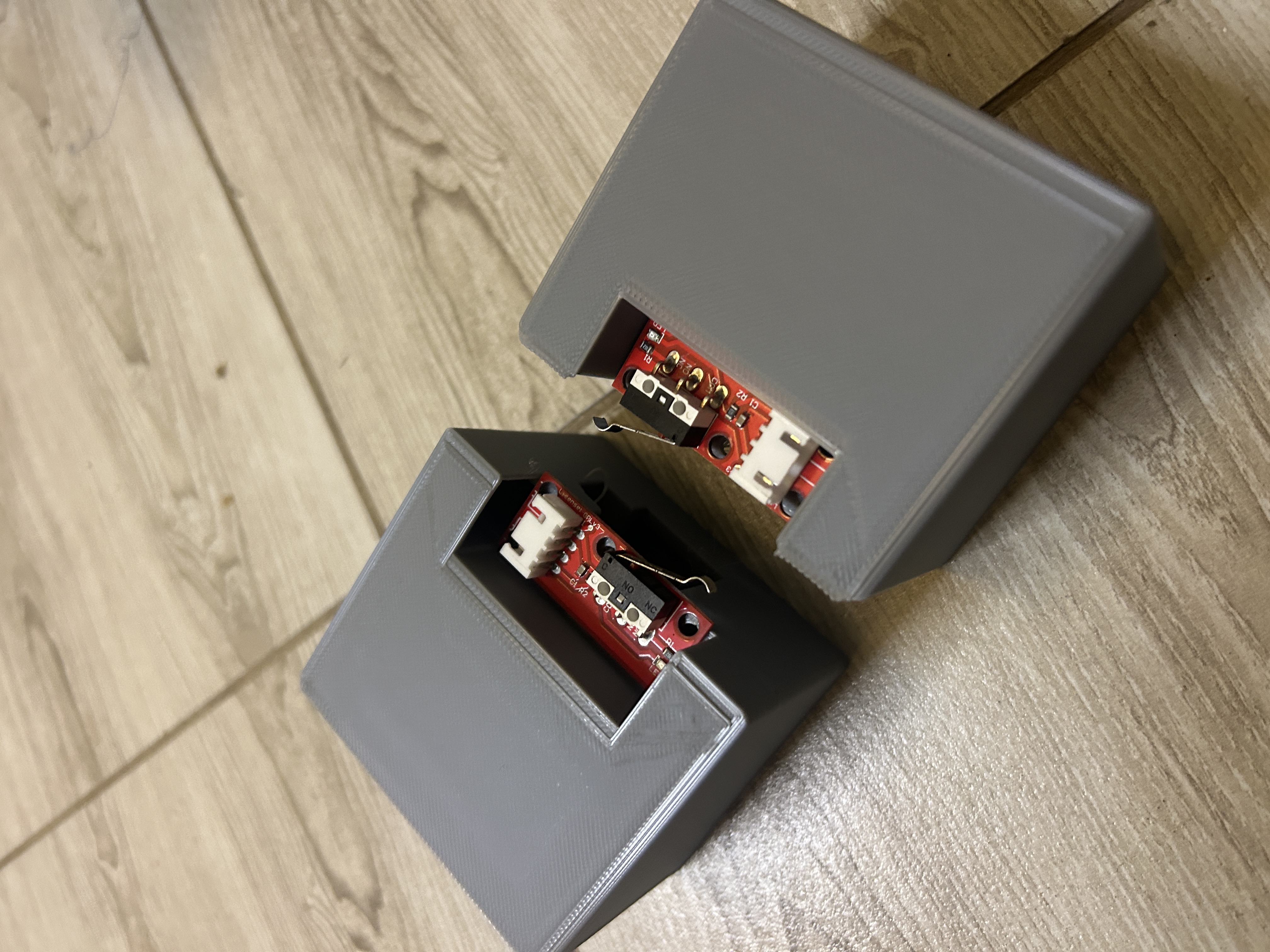
Housing each limit switch in its own printed enclosure made testing much easier. Each one could be positioned and tested independently before mounting it in the final project.
Results, Impact & Performance Metrics
Both switches read reliably with zero false triggers across multiple test presses, each confirmed via serial monitor